You can create simple components like flange couplings quickly and easily in BricsCAD. Simply start with a 2D drawing and use BricsCAD’s intuitive 3D tools to create your 3D model. Let’s take a step-by-step look at how you can create a flange coupling.
Create a circular profile
- First, you’ll need to create a circular profile

- Draw a line starting from the center at a 45 degree angle from the horizontal
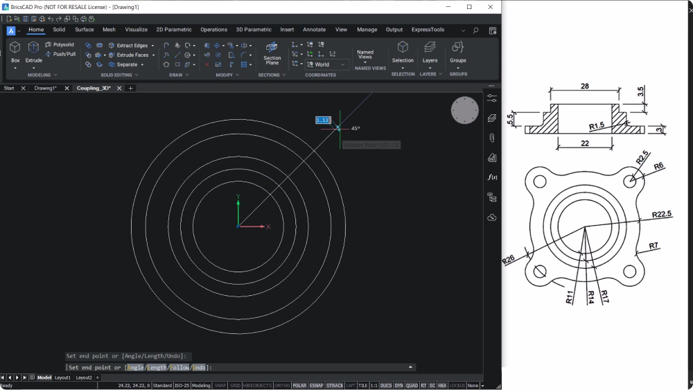
- Create circles with the desired dimensions

- Erase the line and the outer circle
Create arcs
- Fillet the circles to create arcs
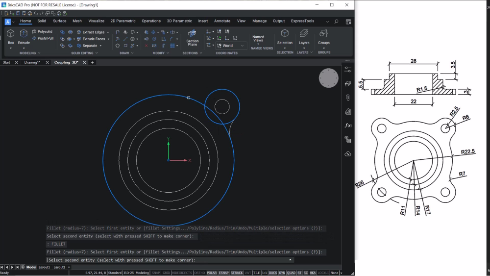
- Choose polar array to copy the entities along the circumference of the circle, aligned with the radius.
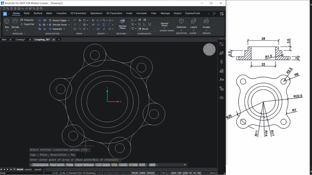
Arrays
- Explode the array entity and use TRIM to remove unwanted portions of the entities
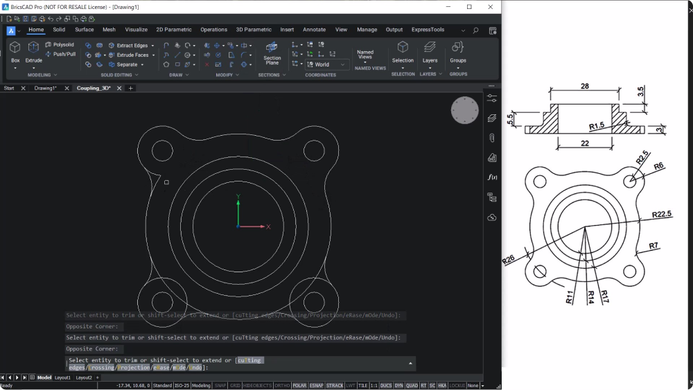
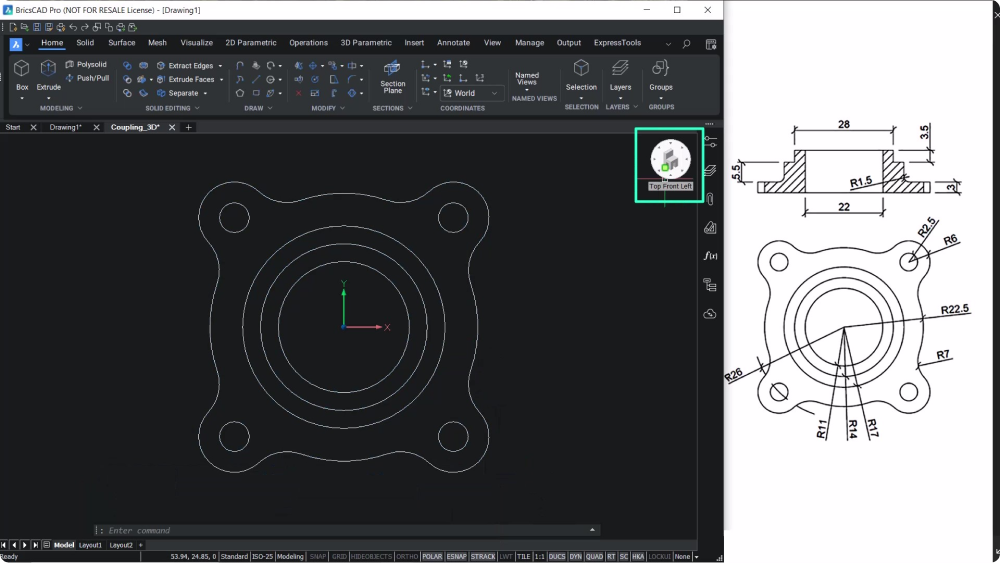
- Join the outer profile to a single entity and take a top, front, left isometric view
Extrude
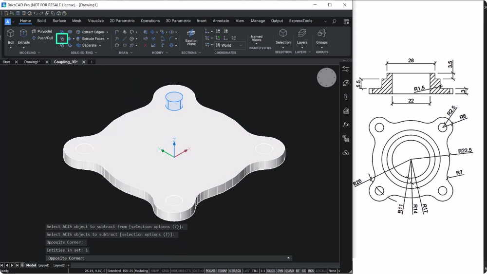
- Use the EXTRUDE command to extrude the outer profile and the inner circles to a distance of 3 units and perform a subtraction
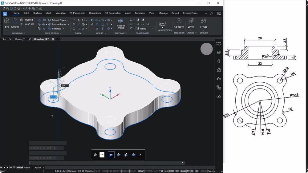
- Copy the inner circle as you will need to use the circle twice while extruding
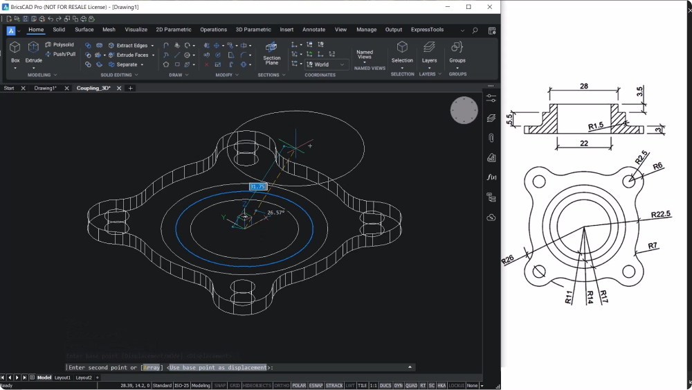
- Extrude the outer and inner circles to a distance of 8.5 units, and subtract the outer solid from the inner solid
- Extrude the remaining circles to a distance of 12 units and subtract the inner solid from the outer solid
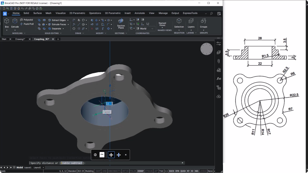
Create a hole
- Take a bottom view of the component and use the Push/Pull tool
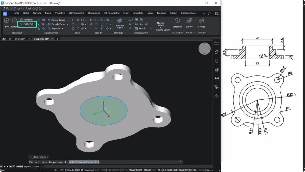
- Pull the circular face upward from the bottom to create a hole
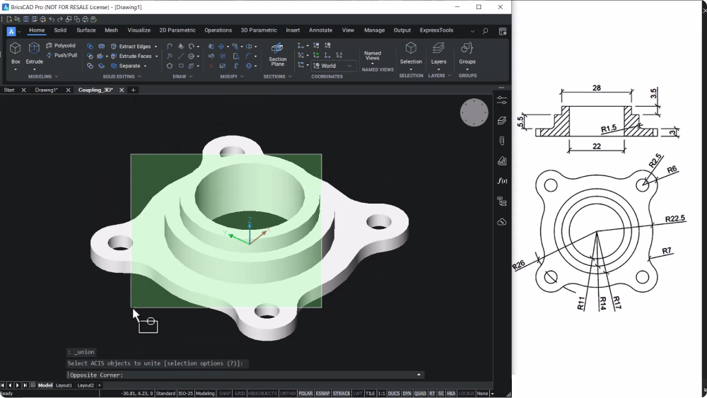
Final touches
- Use the UNION command to union all solids to get a single solid
- Create a fillet at the edge with a radius of 1.5 units
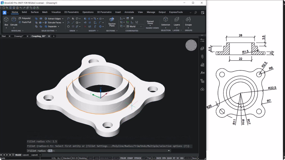
And that’s it! Follow these instructions and you’ll be able to create a flange coupling in minutes.
Discover BricsCAD® BIM
You can try BricsCAD free for 30 days