V23.2 of BricsCAD Pro for Civil has arrived, and it’s chock full of several enhancements to make designing in BricsCAD smoother and more efficient. Let’s go through the enhanced features and how to use them!
The Civil Explorer
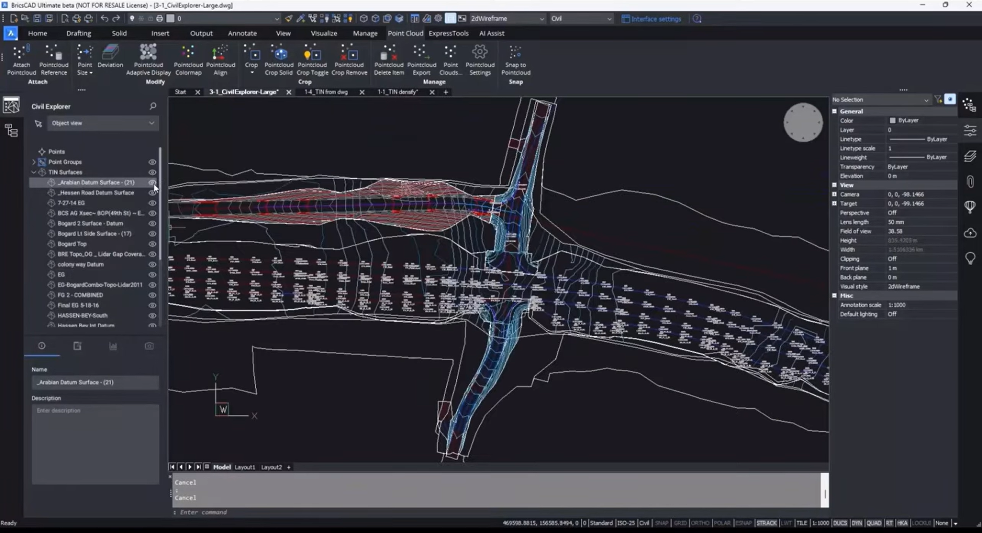
BricsCAD Pro’s Civil Explorer has been revamped and now offers a more intuitive, user-friendly interface that makes it easier to create and manage civil objects. Now, you can create a civil object directly from the Civil Explorer, and you can easily access the object’s properties to make any necessary changes. This streamlined approach will help you to complete your design tasks with fewer clicks and less hassle.
Improved workflow – Building a TIN surface from a DWG
In V23.2, you can now build a TIN surface from a DWG using a much simpler workflow. The new workflow has fewer steps and is more intuitive, making it easier to create a TIN surface from your DWG files. This enhancement will help you to quickly and accurately build your TIN surfaces, saving you valuable time.
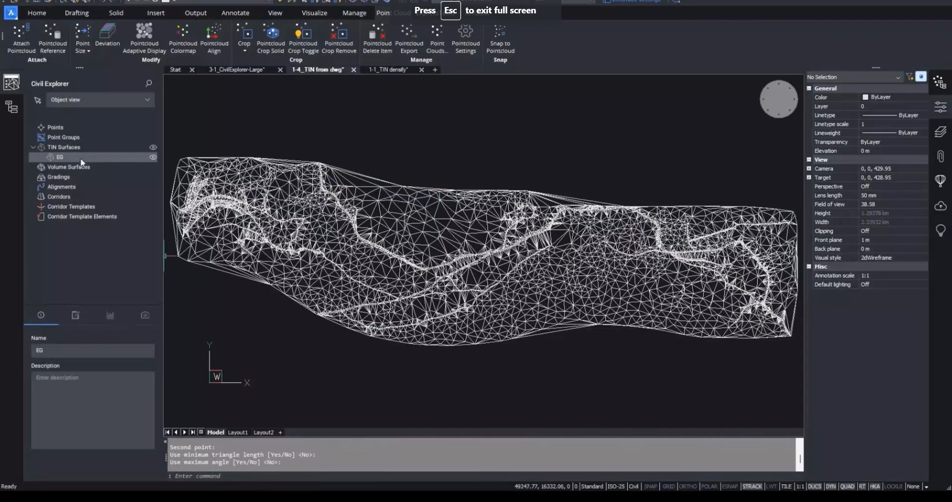
How to create a TIN Surface:
- Open Civil Explorer.
- Expand the TIN Surfaces list.
- Right-click on a surface, and we can zoom in or select that surface. Clicking on the visibility button switches the surface on and off, individually or as a group. This new visibility option applies to other features as well, like alignments or profiles.
- Right-click on TIN Surfaces and click on Create. To build a TIN surface from a DWG, we can just go right-click on TIN surfaces and pick “create”.
- Select the 3D objects that you want to add to the surface.
- Choose to treat linear objects as break lines when prompted.
- The surface will be automatically created.
Enhanced steps editing and parameters used to create a TIN surface
The steps of editing and parameters used to create a TIN surface have been significantly enhanced in V23.2. With this enhancement, you can now specify the properties of your TIN surface more accurately, allowing you to create more precise and detailed surfaces. This feature is particularly useful for those who need to create complex TIN surfaces with high accuracy.
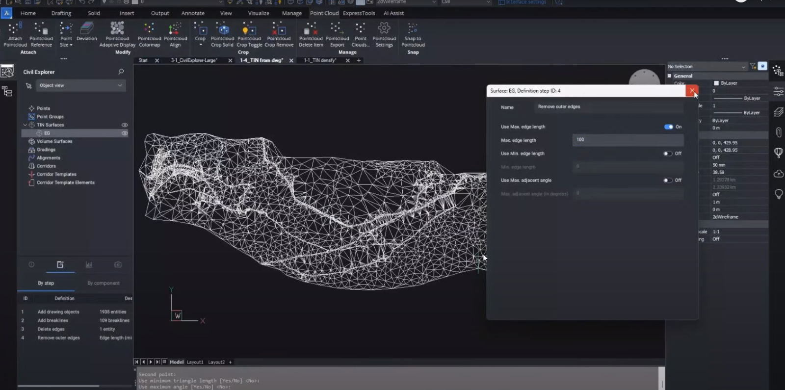
How to clean up the boundaries of the TIN surface:
- Expand the TIN Surfaces list in the Civil Explorer.
- Right-click on the surface you want to clean up.
- Select one of the available options to clean up the edges.
- Add a boundary from a 2D polyline.
- Delete individual lines manually.
- Remove outer edges.
- If you want to remove the outer edges, specify the maximum triangle length.
- Type in a value or just pick something graphically off the screen, and you can see it’s starting to clean up the edges, but it doesn’t work quite as we wanted it yet.
- To make further changes, go to Definitions in the Civil Explorer. This shows all the operations you used to create the surface.
- Double-click on the Remove outer edges command. This will show the value that was input for the maximum edge.
- Change the value of the maximum edge if necessary.
Improved options for working with break lines
Breaklines are essential in Civil design, and in V23.2, the options for working with break lines have been significantly improved. With this enhancement, you can now specify the type of breakline you want to use, the method of insertion, and the properties of the breakline. This feature is particularly useful for those who work with complex Civil designs that require detailed break lines.
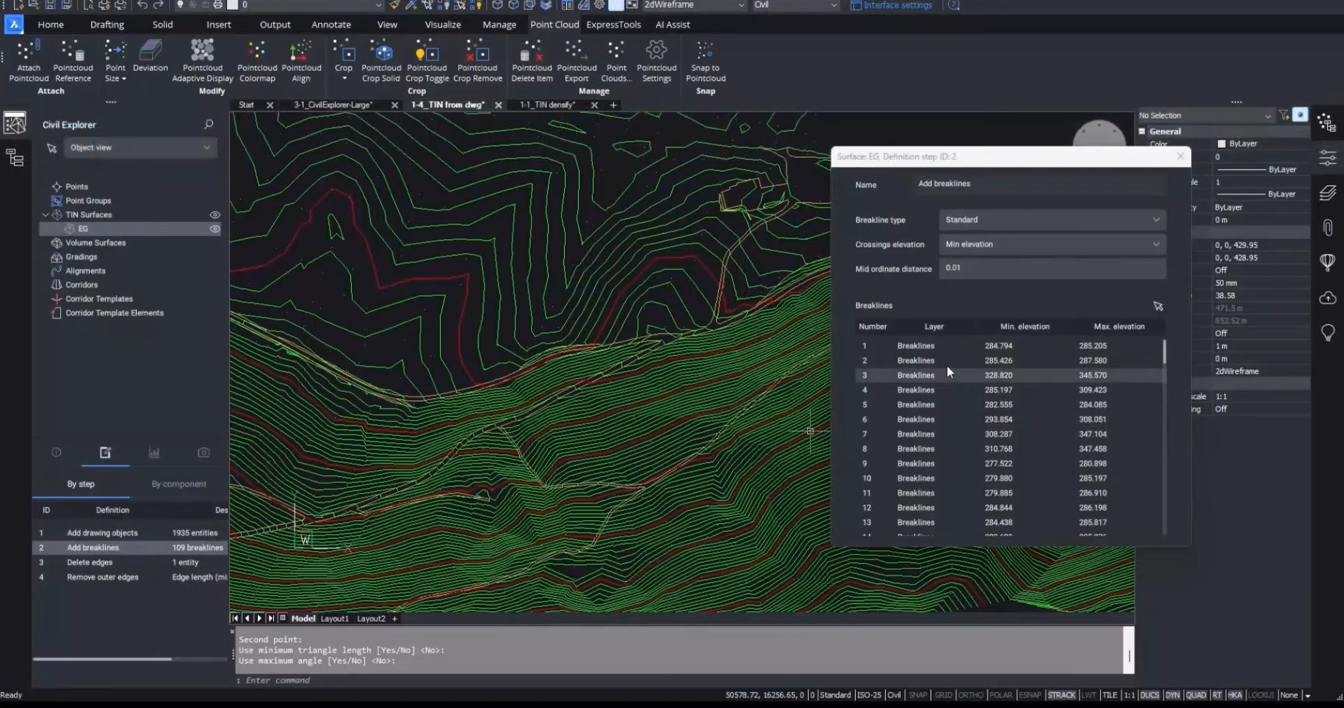
How to view a TIN surface and its breaklines:
- In the Visual Styles panel, turn off the triangles.
- Turn on the contours to view the surface.
- To view breaklines, go to Definitions in the Civil Explorer.
- Double-click on the “Add breaklines” command to view the list of breaklines.
- To select a breakline, right-click on it and choose from the available options.
Improved DENSIFY options – TIN from point clouds
The DENSIFY options for TIN surfaces from point clouds have been significantly enhanced in V23.2. With this enhancement, you can now densify your TIN surfaces from point clouds with greater accuracy and control. This feature is particularly useful for those who need to work with large point cloud data sets to create accurate and detailed TIN surfaces.
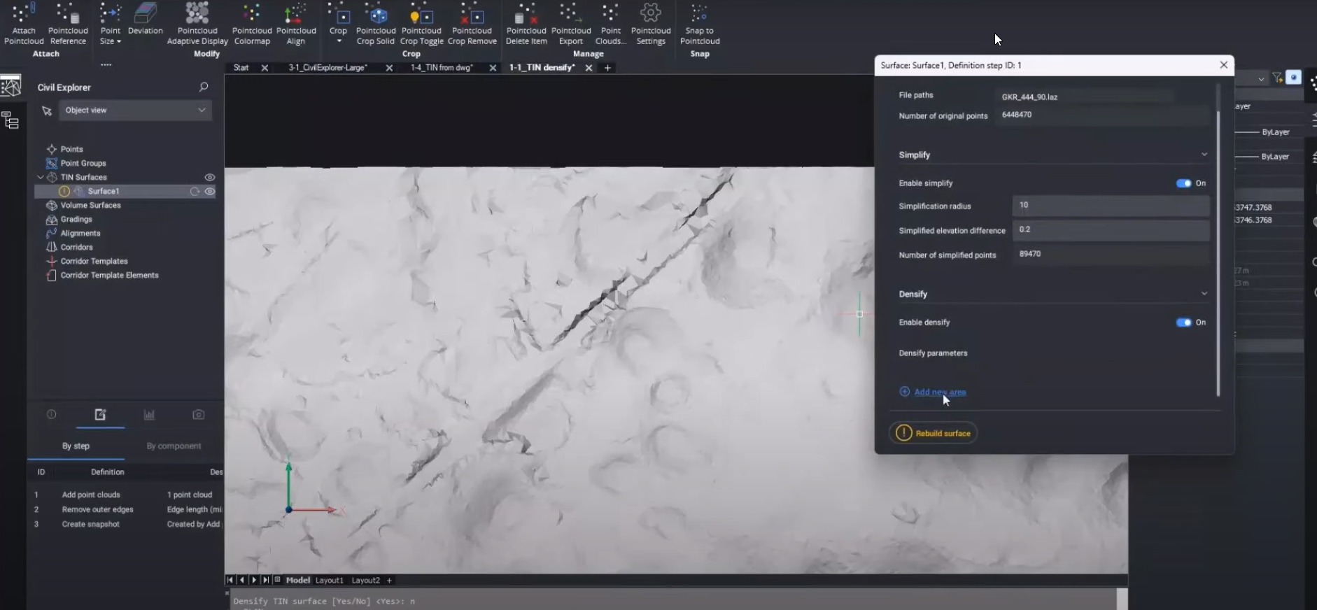
How to densify TIN surfaces from large point-cloud data
- Open BricsCAD Pro and create a new drawing.
- Import your point cloud data by going to the “Insert” tab and clicking “PointCloud”.
- Select the point cloud file you want to use and click “Open”.
- BricsCAD will display the point cloud in the drawing area. You can use the “Navigation” tools to navigate around and zoom in on the point cloud.
- Once you have positioned the view to the desired location, go to the “Civil” tab and click “Create TIN Surface”.
- In the “Create TIN Surface” dialog box, select “PointCloud” as the source data type.
- Choose the point cloud you imported earlier from the drop-down menu.
- Under the “Densify” options, you will see the new “Method” parameter. Select “Delaunay Triangulation” as the method for creating the TIN surface.
- Next, set the desired value for the “Maximum Distance” parameter. This parameter controls how dense the TIN surface will be. A lower value will result in a denser TIN surface.
- You can also set the value for the “Minimum Distance” parameter, which controls the minimum spacing between triangles in the TIN surface. A higher value will result in a smoother TIN surface.
- Once you have set the desired parameters, click “OK” to create the TIN surface.
Watch the video!
Check out the Bricsys YouTube for a full video roundup and walkthrough of these new and enhanced features in V23.2. Watch now!
Have you used tried the new V23.2 features and have some ideas or suggestions?
Fantastic! We love hearing your thoughts on BricsCAD® – all feedback is welcome, whether good or bad. The best way to let us know what you think about BricsCAD or the new V23.2 features is to send us a support request, and our support team will be happy to help.


