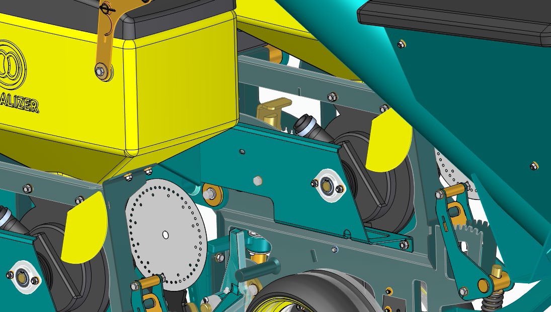
SHEET METAL COMPONENTS CAN HAVE DECEPTIVELY COMPLEX MANUFACTURING PROCESSES, AND THE DESIGN PROCESS ITSELF CAN BE SIMILARLY TRICKY. HOW CAN MODERN TOOLS MAKE IT EASIER TO WORK WITH SHEET METAL DURING BOTH DESIGN AND MANUFACTURING?
The fabrication of components from sheet metal has been practiced for centuries. Today, the ability to take flat sheet metal stock and process it into complex forms is essential for the creation of many different products. The addition of being able to manufacture using numerically controlled machines has not only made the process more efficient, but also made it more powerful as a means to create lightweight and efficient (both in terms of material use and process time) components.
While the sheet metal parts within a given product might range from the single component up to almost the entire product, they’re there and ever present. Sheet metal part design offers a unique set of challenges for the designer or engineer. While the material itself begins in perhaps the most simple of forms (a sheet), the creation of the form to solve the particular design and engineering requirements is, itself, a challenge. On top of this, the requirements for manufacture and for production (for laser cutting, punching, welding and assembly) add further complications. Modern 3D design and engineering software applications
Here are four things to think about when working with sheet metal designs.
1. THE FLAT PATTERN IS KEY
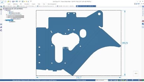
The flat pattern is fundamental to any sheet metal project. It’s possible to model yourself into some interesting corners with sheet metal, creating forms that might look correct in the folded form, but might be entirely un-manufacturable. Having a constantly updated flat pattern means that at any point, it’s possible to unfold the component and check that it can be manufactured. The flat pattern is also fundamental when it comes to both documenting the fabrication process and feeding the data required to the various machines involved. It’s required for conducting nesting operations and resource planning. The output is used as the basis for creation of blanks using laser or water jet cutting technology. Then of course, the fold, bend and stamping positions are required, whether you’re using numerically controlled or manual press brakes. If you’re looking into the world of design for progressive die, then both the flat pattern and 3D model are also fundamental in preparing each stage of the die. Having both an accurate flattened form and a synchronized 3D model are essential.
2. PRODUCTIVITY RISES FOR READING BAKERY SYSTEMS WITH SOLID EDGE
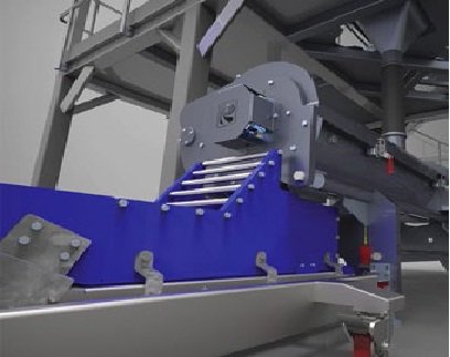
Nestled in the rolling hills of southeastern Pennsylvania, Reading Bakery Systems (RBS) is a supplier of equipment used to produce pretzels, cookies, crackers, biscuits and pet treats. Over 50 years in business, the company has built up a worldwide customer base that includes such well-known companies as Frito-Lay, Nabisco, Keebler and Kellogg’s. RBS, which is based in Robesonia, Pennsylvania, produces a wide-range of equipment, everything from dough mixers to enormous ovens. Its products are not what you’d find in the back of your local bakery. “Our equipment is used for very high-volume production,” explains Michael Cox, manager, Information Technology. In 2003, Reading Bakery Systems replaced AutoCAD with Solid Edge. The company’s management does a good job of tracking engineering productivity and has been able to document a huge productivity increase since switching to the new software. Using AutoCAD, the average time needed to design a part and complete a detailed manufacturing drawing was 3.2 hours. With Solid Edge the same effort requires only 1.2 hours. The company chose Solid Edge for several reasons. Not only did Solid Edge appear to be the easiest solid modeler to use, it also included the powerful assembly modeling and sheet metal design capabilities that RBS required. The switch from 2D to solid modeling brought immediate design advantages, such as parametric modeling and onscreen assembly and interference checking. After only a few projects done in Solid Edge, it was obvious that solid modeling was a faster and more accurate way of designing RBS’ large assemblies and other equipment. One area where the efficiency gains were immediately apparent was in the production of manufacturing drawings. “We used to spend large amounts of time creating assembly drawings; it was difficult and very time-consuming to do in 2D,” Cox says. “Solid Edge eliminates that process. You simply place parts into an assembly and it generates views of assemblies automatically.”
3. SOLID EDGE & SHEET METAL
One of Solid Edge’s secret weapons for sheet metal design is the ability to use a basic 3D model as the starting point to create the form of the sheet metal component – as a volume, just as you would with other prismatic parts. Then, once created, this can be used to ‘wrap’ a sheet metal form around it. This will allow you to define where edges are folded, where they are split, as well as maintaining all of the manufacturing and fabrication parameters. The benefits of this approach really come into their own when design changes need to be made. The underlying body can be quickly edited, then the creation of the sheet metal derivative will propagate those changes. While Solid Edge has the full set of history and feature-based modelling tools we’ve come to expect, it has another ace up its collective sleeve, in the form of synchronous technology. This combines the ease of editing geometry using direct modelling techniques with intelligent and dynamic relationship management. For the user engaged in editing sheet metal forms, this gives specific advantages over the traditional history-based approach. For example, because the system is embedded with the knowledge of sheet metal rules (such as bend radii, constant thickness materials), it allows you to quickly grab faces and edges and push/pull them into position – as opposed to making length edits to explicit features in a history tree. Where this pays real dividends is in the creation of sheet metal parts that confirm to other components in an assembly. Flanges and other features can be quickly ‘snapped’ to reference geometry already in-place – removing the need to first create a sketch of a profile, then extrude or revolve that feature to the required size. Simply create flange, then manipulate the mating face into position. the sheet thickness is maintained as are any bends or folds. In addition to this, Solid Edge’s Live Rules and dimensional constraints allow you to lock down or parameterize these relationships so they are updated during any design changes automatically – without having to worry about how the model was built in the first place.
4 .WORKING WITH 3RD PARTY DATA
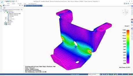
A problem often encountered with sheet metal parts, particularly in the sub-contracting/supply chain, is receiving non-native sheet metal parts in their folded form. Typically, the systems will translate the geometry of such models, but the user typically loses any intelligence relating to how the part is folded upon import. Best in class tools will allow you to work with such ‘dumb’ data and re-feature it, allowing both design edits to be made, but also to create the flat pattern that’s essential. BUILT IN VALIDATION Sheet metal design is typically conducted with a heady mix of, gut feeling for what will work, prior experience and knowledge of the application at hand. For the masters of the subject, these three things are abundant, but for those with less experience, one or more might be missed. This might also be an issue with new hires on the design and engineering team or a new decision to bring sheet metal components into an established product line. Whichever is the case, you should look out for best in class systems which include tools for validation of designs. Whether that’s simple folding/unfolding tests or moving into more advance Finite Element Analysis (FEA) based approaches. Again, systems that include methods that are suitable for the sheet-based nature of sheet metal parts (look out for simulation tools that include shell element modelling techniques) are the most beneficial, both in terms of ease of use and the robustness of the results.
DOCUMENTATION
The final stage in the process, once the folded and flattened forms are designed, iterated and approved, is documentation. Drawings can be created that document the fabrication and assembly process as well as providing input into service documentation as well.
CHECK OUT THE SOLID EDGE FREE TRIAL

