In the manufacturing and assembly world, effectively communicating assembly instructions hinges on the quality of technical documentation. With the release of BricsCAD® Mechanical V24.2, users can benefit from a comprehensive toolkit that enables them to effortlessly document their validated designs.
Create detailed, accurate technical documentation
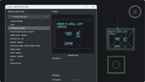
You can quickly generate detailed steps for technical documents using the BMEXPLODE command. Whether you’re an engineer, a technical illustrator, or a marketing specialist, you can leverage the power of BricsCAD Mechanical to create highly effective assembly instruction manuals and maintenance guides.
We updated the BMEXPLODE command in V24.2 to offer enhancements, including new exploded view options based on the current sequence step. This version also considers the user experience by hiding the progress bar during the final input stage for improved clarity.
In V24.2, users can manually position individual assembly components for each specific step in the assembly process. Recognizing the need for focused attention, BricsCAD Mechanical V24.2 allows users to set up custom camera views for individual steps, significantly helping convey the message with precision.
Export documentation to SVG
Since documentation creation often requires word processing, desktop publishing, and layout application programs, the Scalable Vector Graphic (SVG) format is the most suitable choice for exporting the step views. SVG offers users several benefits: scalability, optimal file size, editing capabilities, and predominant style control.
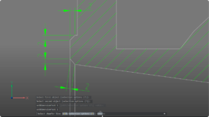
Exporting files to SVG format in BricsCAD Mechanical is straightforward with the EXPORTSVG command. Users gain flexibility in their documentation process with the option to create detailed manual steps or automatic exploded views. Using the BMEXPLODE command and selecting the auto option gives users a generalized view of the product disassembly. You can add further details, like a part’s path during assembly, by adding trailing lines using the BMTRAILINGLINES command.
Highlighting Optimum Assembly Orientation
Learning from the gravitational stability results during inspection can help optimize the assembly instructions. For example, suppose steps resulted in an unstable outcome in an upright orientation. In that case, you may need to ensure the assembly is oriented in a flat position so the fasteners can be inserted top-down.
Tools like the manual detailed exploded view can help you create a virtual environment (like a workbench) to highlight the best assembly orientation. The final stage involves importing the SVG files into the assembly manual document, documenting the assembly steps, and including essential details like the ideal orientation for assembly.