We have given the OPTIMIZE command a UI overhaul both for 2D and 3D designs. OPTIMIZE calculates the gap tolerance to close the gaps, fix inaccuracies in the drawing, and works in both 2D and 3D spaces. Let’s take a look!
Checking drawing details
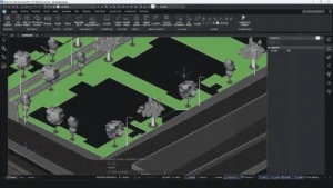
In this example you can see that there are many gaps between lines, or the lines are skewed and tilted.

You can check how tilted a line is by viewing the properties panel. In this example, some objects are close to a rounded value, but they aren’t actually rounded.
It’s clear that we will have a lot of work on this drawing to make it workable and to make it more accurate. So, OPTIMIZE to the rescue!
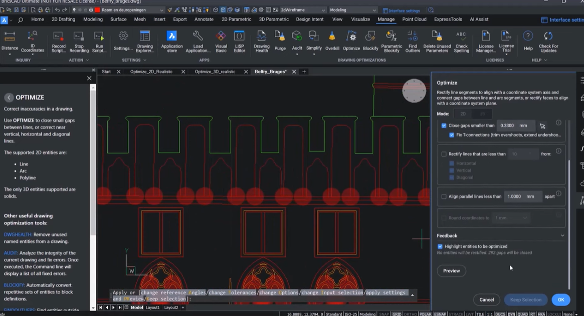
Preview the drawing
OPTIMIZE improves many aspects of the drawing. You can preview these improvements by clicking the preview button to give you a full understanding of what will happen once you optimize the drawing.
Once you have checked the preview, you can see where you may need to tweak the settings to fix any remaining skewed lines or gaps which haven’t closed to get a better result.

Optimize Settings
You will need to decide how big you want the gaps to be to close. BricsCAD has a new picker which lets you specify two points in the drawing, from which it calculates the gap tolerance. Any gaps closer than this tolerance will be closed.
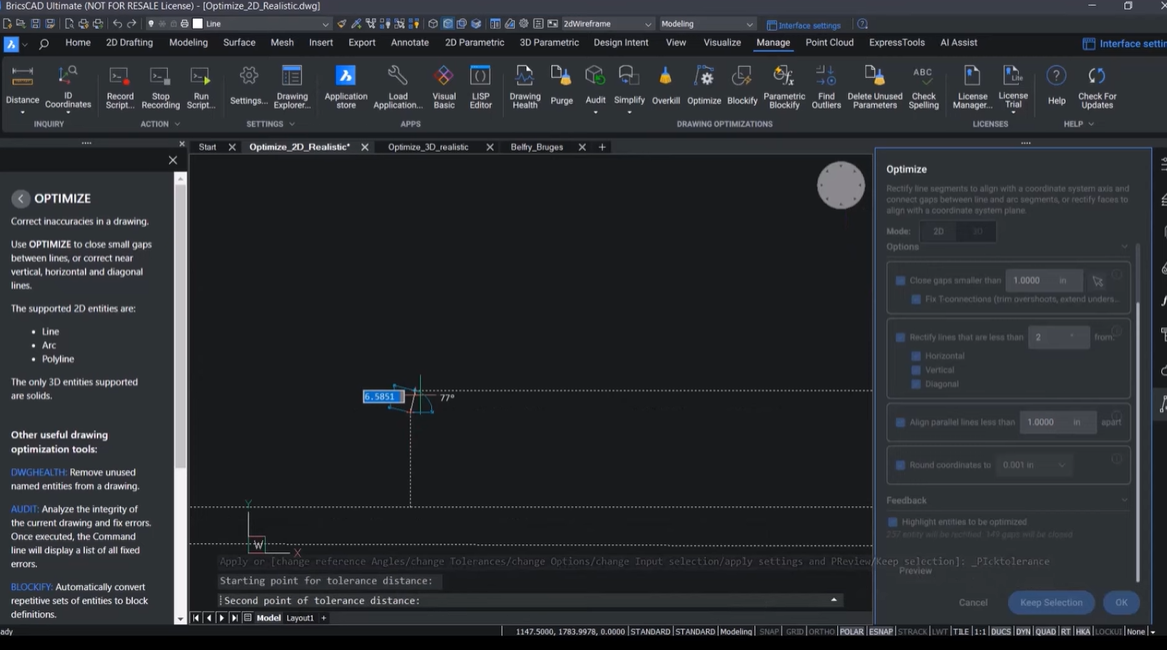
This is visualized in your drawing with red circles.
You can also change the angle tolerance to optimize lines and change the rounding tolerance to one edge. This will close more gaps and rectify more skewed lines. Check the properties panel to see how the end points of the line are optimized to the closest integer.
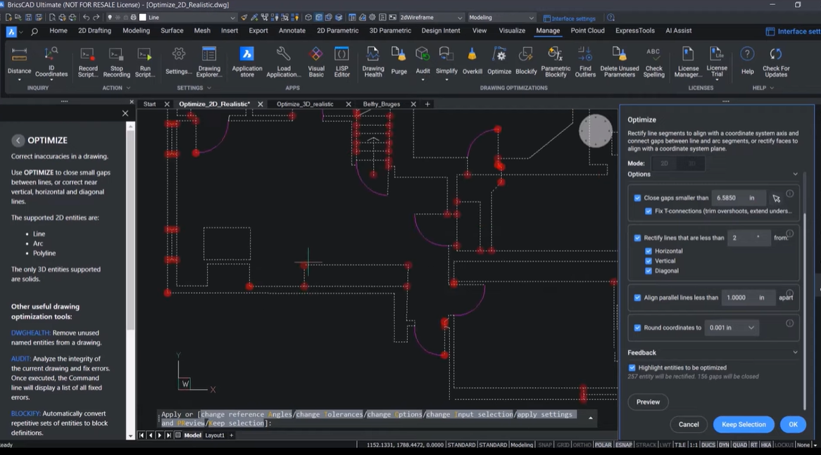
Individual Optmization
The options in the OPTIMIZE command can also be used individually thanks to the command’s new dash UI. Take for example this drawing of The Belfry in Bruges, Belgium. In reality, the building does not consist of straight lines – but there are still some inaccuracies that need to be fixed.
Once OPTIMIZE has calculated the initial possible optimizations, you can see the command panel launches.
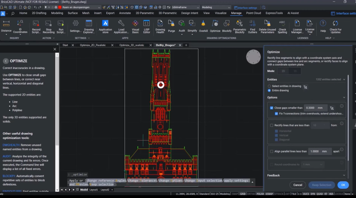
Here, red circles indicate the size of the gaps that need to be closed.
You can check the gap size to see if you are happy with it and change it if needed. Then, you can single click to see that these inaccuracies have been resolved.
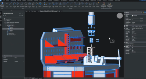
Otimize for 3D
OPTIMIZE has undergone the same UI overhaul for 3D as in 2D, with settings logically grouped together. Let’s now look at a 3D example.

You can see that some of the faces of these solids are not optimal. Here you can see the slope of this face is 0.12 instead of 0.
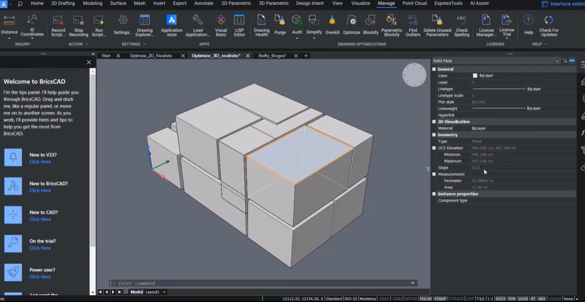
When looking at the front, you can see that certain faces are not fully coplanar.
For this example, let’s say that you only want to straighten faces which are parallel to the XY plane. You can check in the properties panel that the slope of all these faces is exactly 0.
Here you can see that these faces are still not coplanar. To fix this, you can use OPTIMIZE again, choosing the “Align parallel faces” option, you can also round them. After doing this and selecting multiple faces, you can now see that the slope is 0 and that the UCS elevation is exactly the same.

Watch the Video
Check out the YouTube walkthrough to watch the OPTIMIZE command in action!
Have you used or tried the new V23.2 features and have some ideas or suggestions?
Fantastic! We love hearing your thoughts on BricsCAD® – all feedback is welcome, whether good or bad. The best way to let us know what you think about BricsCAD or the new V23.2 features is to send us a support request, and our support team will be happy to help.